Waypoints Mission: plan a flight route and capture photos or videos at waypoints along the route.
Mapping Mission: collect images of an area to reconstruct a 2D model.
Oblique Mission: collect images of an area from multiple camera angles to reconstruct a 3D model.
Corridor Mission: collect images of a corridor (e.g. rivers, railroads) to reconstruct a 2D model.
Detailed Inspection Mission: Set target points on a reconstructed model and a flight route will be automatically generated, allowing the aircraft to capture photos at these target points.
DJI Terra’s Oblique Mission uses 5 flight routes to capture the same amount of data as using 5 cameras simultaneously on a drone. The 5 flight routes correspond to the 5 camera headings – downward, forward, backward, leftward, and rightward.
If you have access to a mobile device that has an internet connection (such as a cellphone), you can turn on the hotspot so that the laptop can be connected to the internet.
If the site where you are operating has no internet signal, you can pre-plan the flight route while you are indoors and have an internet connection, or manually fly the drone around the area to be mapped to set boundaries points to plan flight routes.
In photogrammetry and remote sensing, ground sample distance (GSD) in an aerial digital photo (such as an orthophoto) of the ground is the actual distance on the ground captured as represented by pixels. The unit is cm/pixel.
Mission Relative Height in Advanced Settings is the height of the takeoff point relative to the area being mapped.
Mission Altitude is the height of the drone relative to the area being mapped, which is also how ground sample distance (GSD) is calculated.
When there is a large difference between the elevation of the takeoff location and the elevation of the area being mapped, you can adjust the Mission Relative Height in Advanced Settings to ensure that the Mission Altitude is determined considering the elevation of the area being mapped.
Please see the attached illustration: If the drone takes off from a 50 m building marked H1 in the illustration, the area being mapped is marked A, and the expected altitude for aerial data collection is 100 m, you can set the Mission Altitude in Basic Settings to 100 m, and Mission Relative Height in Advanced Settings to 50 m.
Similarly, if the drone takes off from H2 to map area B, which is a hill with an elevation of 40 m, and the expected altitude for aerial data collection is 60 m, then set Mission Altitude to be 60m, and Mission Relative Height to be -40 m.
It is recommended to have a forward overlap rate of 80% and a side overlap rate of 70%, which should meet the requirements for most application scenarios. The overlap rate can be increased when the area being mapped has a large difference in elevation to ensure the highest point mapped has enough overlap. When the area mapped is relatively uniform in elevation, the overlap rate can be adjusted lower to reduce the amount of data that needs to be processed, making the mapping mission more efficient. However, it is recommended to keep the forward overlap at a minimum of 65% and side overlap at a minimum of 60%.
Phantom 4 RTK and Matrice 300 RTK.
Yes, LAS point cloud files can be imported.
Yes. You should set the coordinate system when you first import the file. If the file uses an arbitrary coordinate system, you need to correct it using third-party point cloud correction software.
No, the aircraft needs to be flown at absolute altitude.
1. Make sure the RTK data sources are consistent when planning or executing a flight path;
2. Flight paths can only be executed when the RTK is in FIX status. During execution, you may set the first waypoint as the hovering inspection point. The mission must be stopped if the location of the inspection point is incorrect.
First make sure if the number of images transmitted differ significantly from the number of images shot. If they do not, you may check the log to see if a “relocalization fail” message has appeared. If so, you need to increase the mission altitude as necessary to enhance the overlap rate.
The Field Scenario is designed to capture data from a relatively flat land, for example rice or wheat fields.
The Urban Scenario is designed for areas with buildings of different heights.
The Fruit Tree Scenario is designed for orchards that might have a large variation of elevations and heights.
The 2D mapping algorithms are optimized for the three specific scenarios, so you can choose the one that best fits your mission type.
1. The head of the aircraft did not turn around during data acquisition, and the intrinsic parameter cx or cy of the aircraft is shown in the aerotriangulation quality report as >5% than half the length and width of the images;
2. The locations cover contrasting terrain, with roofs or hilltops captured in the shots, which resulted in a low overlap rate. You may re-shoot the images as needed.
1. The overlap rate is too low. You may re-shoot the images as needed;
2. Make sure “Urban” is selected as the reconstruction scenario.
The location information on aerial images collected by a drone that’s not equipped with RTK is not the most accurate, which will result in a difference between the elevation in the digital surface model (DSM) and the actual elevation.
When conducting missions with the Phantom 4 RTK, if the 2D map is generated with only the Nadir view images collected, the precision of the DSM will be limited, which is why it is recommended to incorporate oblique imagery in building the 2D map to enhance precision. This can be done by setting the gimbal pitch to -45° and circling the point of interest during flight.
There are three options for reconstruction resolution: high, medium, and low, which will generate models at full, half, and quarter resolution respectively. The higher the resolution the better the quality of the reconstructed models. The rough ratio of time consumption for reconstruction at high:medium: low resolutions is about 16:4:1.
Yes, this can be achieved before reconstruction. After aerial triangulation optimization is complete, crop 2D and 3D models by specifying the reconstruction area using the ROI modeling function.
Gaps in the model can be due to missing shots of the area being mapped, or images taken at poor angles. The quality of reconstruction can be affected by factors such as reflective surfaces in the area (water or glass), or large areas of the same color or pattern (white walls, skies).
You will need to define the camera parameters of each of the five cameras. The captured photos will be stored in five folders corresponding to each lens.
In a folder, select all photos, right-click and go to Properties, click Details, scroll down to Camera Model, double-click the parameter value box on the right to go into edit mode, enter numbers or letters. Do this in all five folders for the five camears, the names should be different for each camera, for example it can be set to: 1, 2, 3, 4, 5 or A, B, C, D, E.
The head of the aircraft did not turn around during data acquisition, and the intrinsic parameter cx or cy of the aircraft is shown in the aerotriangulation quality report as >5% than half the length and width of the images.
The tilted shots are missing. You may recapture the images as needed.
The spots may be caused by damage to your SD card or camera.
1. Your RAM may be running low. Currently the processing speed is roughly 300-400 images/G, with no block partitions for aerotriangulation. Divide the number of images imported by 300, and see if the result is greater than the current available RAM;
2. The overlap rate of the images is too low. Has the overlap rate been adjusted to a lower level? Were there any big altitude changes? The overlap rate may need to be increased for areas with greater altitude changes;
3. The textures of objects are not captured in the images: Overexposure of water surfaces, white walls, the sky, snowy grounds, stadiums or other large structures under the sun;
4. Repeated texture: Rice fields, solar panels, floor tiles, etc.;
5. A large number of objects were in motion: Crowds, vehicle flows, sea waves, etc.;
6. A large area captured in the image consists of objects not made of diffuse reflective materials: Mirrors, glass, reflective car surfaces, etc.;
7. The angles of view differ greatly between the images (5-camera oblique system). The top-view image has been reconstructed, but most of the images for the tilted angles are lost;
8. Image quality issues: Blurry movements, lack of focus, overexposure, etc.;
9. Non-continuity in the images, missing shots, or importing multiple sets of data not applicable to the same area.
1. Import the images into DJI Terra, and check their 2D locations on the map;
– Multiple missions can be created to reconstruct the images separately if they are not continuous and can be clearly categorized into batches
– You may capture additional images to fill in shots that may have been missed
2. The 2D locations of the images are continuous and do not show noticeable gaps;
– The reconstruction success rate is relatively low for images of large bodies of water such as the ocean; while for rivers and lakes, you should increase your mission altitude and make sure no more than 1/3 of any single photo is covered by water
– You may recapture the images if the locations are in hilly terrain and the overlap rate is lower than 60%. You should fly the aircraft at a higher altitude and ensure a sufficient overlap rate
3. Data was recorded from multiple trips, and the overlap rate between the trips is sufficient. Some trips do not appear in the reconstruction, while each trip can be reconstructed individually.
– The lighting conditions should not differ too much between the environments where the data was acquired. If some trips were recorded in the morning, while others were captured in the afternoon, the software may not be able to merge the data of different trips due to big contrasts in brightness
1. Glass and car surfaces are not made of diffuse reflective materials. You may try shooting the images at a greater distance;
2. White walls and lake surfaces do not have textures. You may try shooting the images at a greater distance.
2D reconstructions:
Results include map tiles shown in the app’s interface, digital orthophoto maps, and digital surface models in the GeoTIFF format used in UTM projections.
3D reconstructions:
Results contain a level of detail model in .osgb, .b3dm, or .s3mb, texture mesh in .ply, .obj, or .i3s, a point cloud in .pnts, .las, or .s3mb, and an aerial triangulation result file in .xml or Terra’s own format.
The accuracy of the reconstruction can be affected by factors such as camera distortion, image quality, flight height, side and forward overlap settings, GPS (RTK) positioning accuracy and the area’s texture information.
You can click the Open folder button in each Mission to open the file folders where the files generated from the missions are stored. Aerotriangulation results are stored under “AT”, 2D maps are stored under “map” and 3D point cloud or models are stored under “models”.
To view log files of reconstruction mission using Standalone computation, use Ctrl + Alt + L.
Due to limitations in the computer’s processing capacity, you can only run multiple reconstructions at the same time. They will be processed in the order in which they are added to the lineup.
Please update the GPU driver.
To build reconstruction models as quickly as possible, DJI Terra uses all the computer resources available, including the CPU, RAM, and VRAM of the graphics card, which could make the computer slower while running DJI Terra but should not be a problem once the processing is finished.
It is recommended that you don’t run other programs that might be GPU-intensive while running DJI Terra, as doing so could result in failure of model reconstruction.
Yes. After completing an aerotriangulation, you can set your region of interest and begin reconstruction.
To allow a .prj file to be imported into DJI Terra, you must ensure the file follows a Esri-supported format and its projection or coordinate framework data are described in WKT character strings.
1. Some of the value for horizontal or vertical accuracy in the POS data of your imported images is 0;
2. The horizontal or vertical accuracy for the image GCP is set at 0 (we recommend updating to version 2.2.1 and above which has an automatic fault tolerance mechanism).
Yes, after 3D reconstruction is complete, you can continue reconstruction by checking the required output format.
Please refer to Preparation Before Using DJI Terra available on the download page.
Please refer to Preparation Before Using DJI Terra available on the download page.
Depending on the highest computer RAM configuration, 1GB of free RAM can handle 8 gigapixels of data (approximately 400 Phantom 4 RTK images).
Each computer connected to a local network is either a control device or a worker device. A control device assigns reconstruction missions (and also undertakes part of the computing work), while reconstruction algorithms run mainly on worker device.
Binding is not necessary. Worker devices can be replaced as needed.
Yes. For details, please refer to Preparation Before Using DJI Terra.
DJI TERRA ENGINE
It is used to store original image data, temporary outputs and reconstruction outputs.
Currently supported during the feature point matching phase. Other phases will be computed using the worker device with the highest RAM.
The reconstruction mission list displays the status of the worker devices currently participating in the reconstruction.
Aerotriangulation: Automatically selects the worker device with the highest RAM to perform the aerotriangulation missions;
Block reconstruction: When the number of blocks is larger than the number of worker devices, the worker devices will be used to the maximum extent.
No. To enable a restarted or released worker devices to participate in the current reconstruction mission, you can stop the mission and re-select the devices before continuing reconstruction.
Temporarily not to the step of using a discrete graphics card (integrated graphics cards are not used for computing on DJI Terra).
Download and install the application: https://download.microsoft.com/download/2/E/6/2E61CFA4-993B-4DD4-91DA-3737CD5CD6E3/vcredist_x64.exe
1. Ensure that the Shared Directory of the control devices and worker devices are consistent and the paths are accessible;
2. Close the antivirus software and security software, then try searching again;
3. Disable the firewall of the control and worker devices.
4. Try searching again after disabling the virtual network card (Network Settings → Change Adapter Option → Disable Networks Started with Hyper-V).
No, the photos and existing aerotriangulation results will be automatically copied to the network-attached storage (NAS) for cluster reconstruction.
1. First, check if you are using software such as Microsoft OneDrive, Outlook, Microsoft Teams and Flash. The software can be uninstalled if not needed;
2. If it is needed, you can try:
(1) Updating the above software
(2) Updating the Win10 system
(3) Updating the driver
(4) Performing the setting: IE security policy-allow dynamic scripts
(5) Performing the setting: IE advanced settings-reset
A single worker device error will not cause the reconstruction mission to fail. Any failed worker device mission will be redistributed by the control device. If the redistributed worker device also has errors, the reconstruction mission will fail.
1. In the control device, open DJI Terra, press Ctrl+Alt+L, find all logs for the corresponding time period of the failed mission in the folder and export the logs;
2. Under the shared directory, find all logs of the log folder [slaves_log] corresponding to the mission and export them;
3. SDK_log.txt in the models (3D) or map (2D) folder in the cache directory of that mission.
The reconstruction process is divided into several stages which should be carried out in sequence. Some stages are completed independently on the control device, at which point all worker devices will be in the preparing state.
Some stages are split into multiple missions which are then assigned to the worker device for processing. The worker devices that have completed the missions assigned will be in the preparing state, and will enter the next reconstruction stage after the other worker devices have also completed their processing.
The following reconstruction results can be delivered in specified coordinate systems.
2D Reconstruction Results: dsm.tif、result.tif
3D Reconstruction Results: LAS files, OBJ files, PLY files, OSGB files, PCD files, S3MB files, I3S files. Each file comes with a coordinate system instruction file metadata.xml.
This error will pop up if reconstruction results cannot be converted to the specified coordinate system. The output coordinate system has to do with GPS information on the images and the coordinate system the GCPs are in. Here are some scenarios that you might want to consider:
(1) Aerial triangulation without GCPs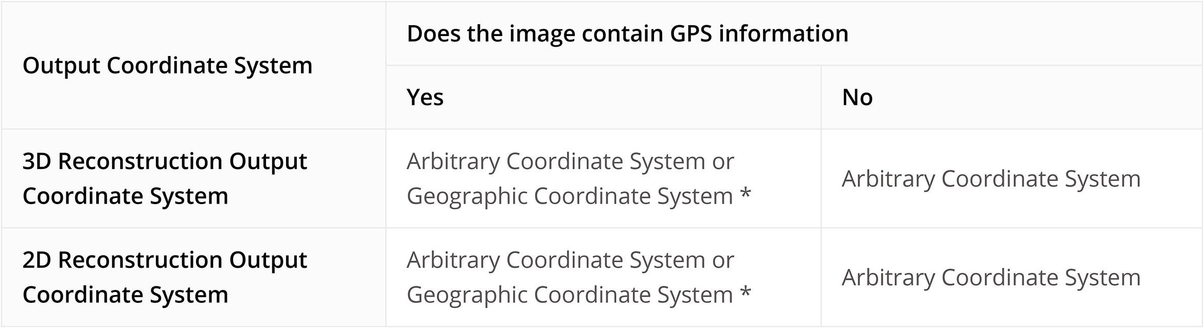
(2) Aerial triangulation optimized with GCPs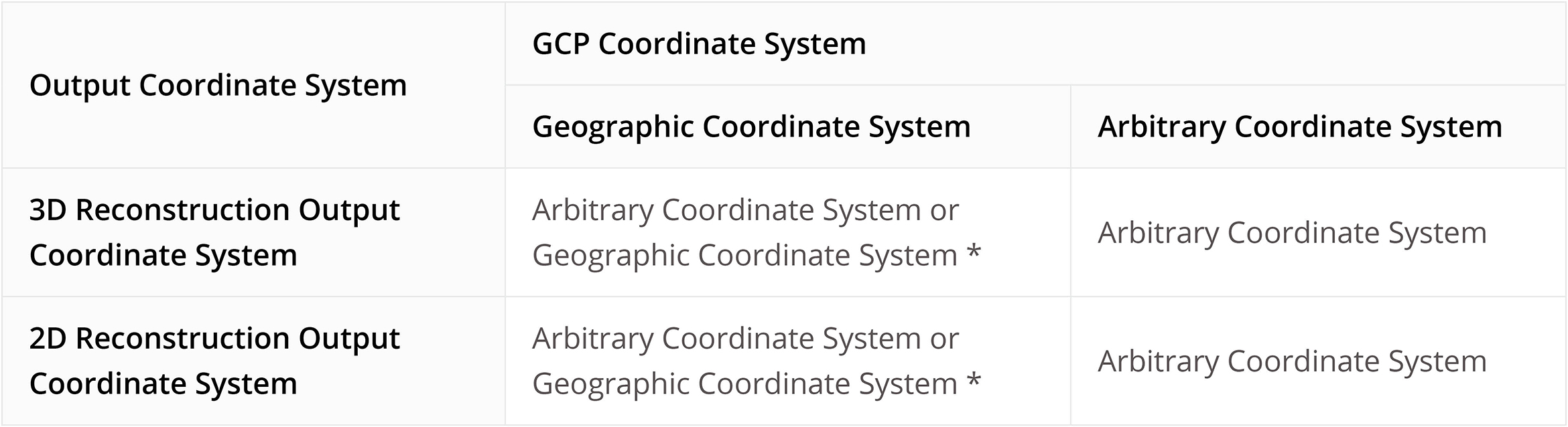
Ground Control Points (GCPs) are marked points on the ground with known coordinates and are clearly visible in an image. GCPs can be obtained using photogrammetry methods such as GPS-RTK or a total station.
GCPs help increase the robustness and accuracy of aerial triangulation, check the accuracy of the aerial triangulation against actual measurements, and determine absolute orientation by converting the aerial triangulation result into GCPs in the designated coordinate system.
The GCP data should be in this order: point name, latitude/X, longitude/Y, height/Z, horizontal accuracy, vertical accuracy).Accuracy data is optional. The first row is coordinate data, and each column is separated with a space or a tab. In the projected coordinate system, X represents the East, and Y represents the North.
GCPs are used to optimize the result of aerial triangulation. It would take at least three GCPs to ensure absolute orientation for aerial triangulation.
Check points are used to check for the absolute accuracy of aerial triangulation by comparing the error between the result calculated with aerial triangulation and the actual measurements.
It is recommended to use no less than four GCPs for calculation in each target area.
When you have an abundant number of GCPs, you can choose to set some of them as check points to check for accuracy.
GCPs values are used in aerial triangulation, and the accuracy should correspond to the final absolute accuracy that your project needs.
The smaller the accuracy settings, the stronger the GCP’s contribution will be to the triangulation model.
When computing a point and GCPs have been marked on at least 2 images, the 3D coordinates will be calculated and reprojected onto all images in which the point appears. The difference between the marked point and reprojected point on the image is the reprojection error. the average of different reprojection errors is shown in DJI Terra as the reprojection error.
The 3D error of a GCP refers to the spatial difference between its measured coordinates and 3D coordinates obtained by conducting space intersection with the elements of interior and exterior orientations of the image.
Given that the coordinate system in which aerial images and GCPs have been acquired can be converted using DJI Terra, i.e. the images and GCPs use the same coordinate system geodetic datum:
a) For images with high positioning accuracy, for instance, ones acquired using the Phantom 4 RTK, GCP projections will not be far off from actual measurements. Mark the GCPs with reference to their projected results on the image, and then click “aerial triangulation” on the screen.
b) For images with low positioning precision, you can run aerial triangulation first with the imported images that contain GPS information, and then import the measured coordinates of the GCPs. After the first triangulation, you can proceed with marking the GCPs and run an optimization by pressing “optimize” on the screen.
An optimization is done to improve results of aerial triangulation. If a triangulation is done immediately after marking GCPs, check points will also be used in the calculation, which is not ideal. A better process will be: aerial triangulation enter GCP coordinates and mark them against projected coordinates on the image optimize. By doing so, GCPs are used to improve the accuracy of aerial triangulation.
Make sure the positioning and attitude information of the imported images is correct.
Make sure the positioning and attitude information on the images are correct, and choose the same coordinate system as the one that the GCPs are set in.
The accuracy of aerial triangulation and optimization are affected by three factors: error in GCP marking, error in coordinate measurement, and the distribution and number of GCPs within the mapping area.
We recommend you choose at least four GCPs distributed evenly across the target area. Each GCP should appear in at least four images at different locations, and avoid having it near the edge of an image.
1. The coordinate systems do not match. Make sure the coordinate system of the GCPs is the same as that of the selected GCPs, and the coordinate system of the imported POS data is the same as the selected POS data.
2. The coordinate systems cannot be converted from one to the other. Make sure the coordinate system of the image POS data can be converted into the coordinate system of the GCPs. If not, please convert systems using a third-party software program.
3. Height errors. Check the height differences between the coordinate systems of the imported POS data and GCPs. If there are errors, adjust them in the POS data settings.
1. If you are looking to acquire results in a particular height or coordinate system (e.g. a local height or coordinate system that might not be included in Terra’s existing database) without GCPs.
2. If you are looking to process POS data and GCPs in the same height or coordinate system, you might need to import POS data and GCP data that have already been converted to said system.
The coordinate system setting of the POS data needs to correspond to the actual system written in the data. Any height errors need to be adjusted for in the settings. You can preview the height values after adjusting all the POS import settings.
1. Set to default DJI Terra accuracy. If the images contain RTK information and it is fixed, DJI Terra will read this data automatically and set the accuracy as follows: horizontal accuracy: 0.03 m, elevation accuracy: 0.06 m. If no RTK information is available or if it is not fixed, horizontal accuracy will be set to 2 m and vertical accuracy 10 m.
2. Set accuracy values manually. Edit the horizontal and vertical accuracy values into the POS data files and choose the corresponding column in in the POS import settings.
These images will not be included in aerial triangulation calculations.
Generally, you should keep it on, but turn it off if the image POS data and the GCPs are not in the same height system.
No, LiDAR point cloud is a free feature, but if you need to use the point cloud accuracy optimization feature, you need to purchase the license for the professional version or higher.
mported folders must include LiDAR point cloud data, RTK data, IMU data, whereas JPEG data can be imported when needed (select the folder named after data collection time).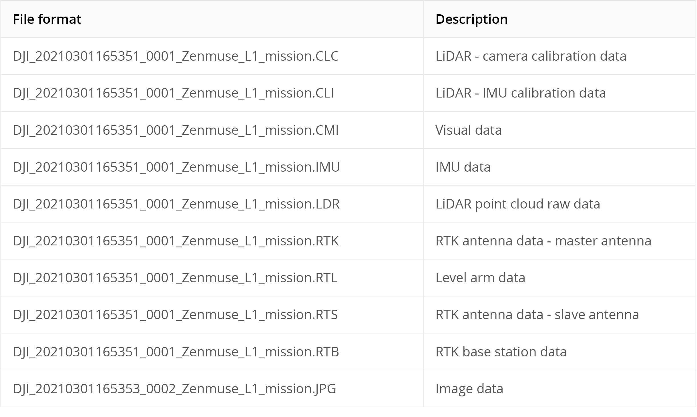
The format for the route document will be in .out, a SBET and a SMRMSG document, and the format definition is as follows:
SBET Format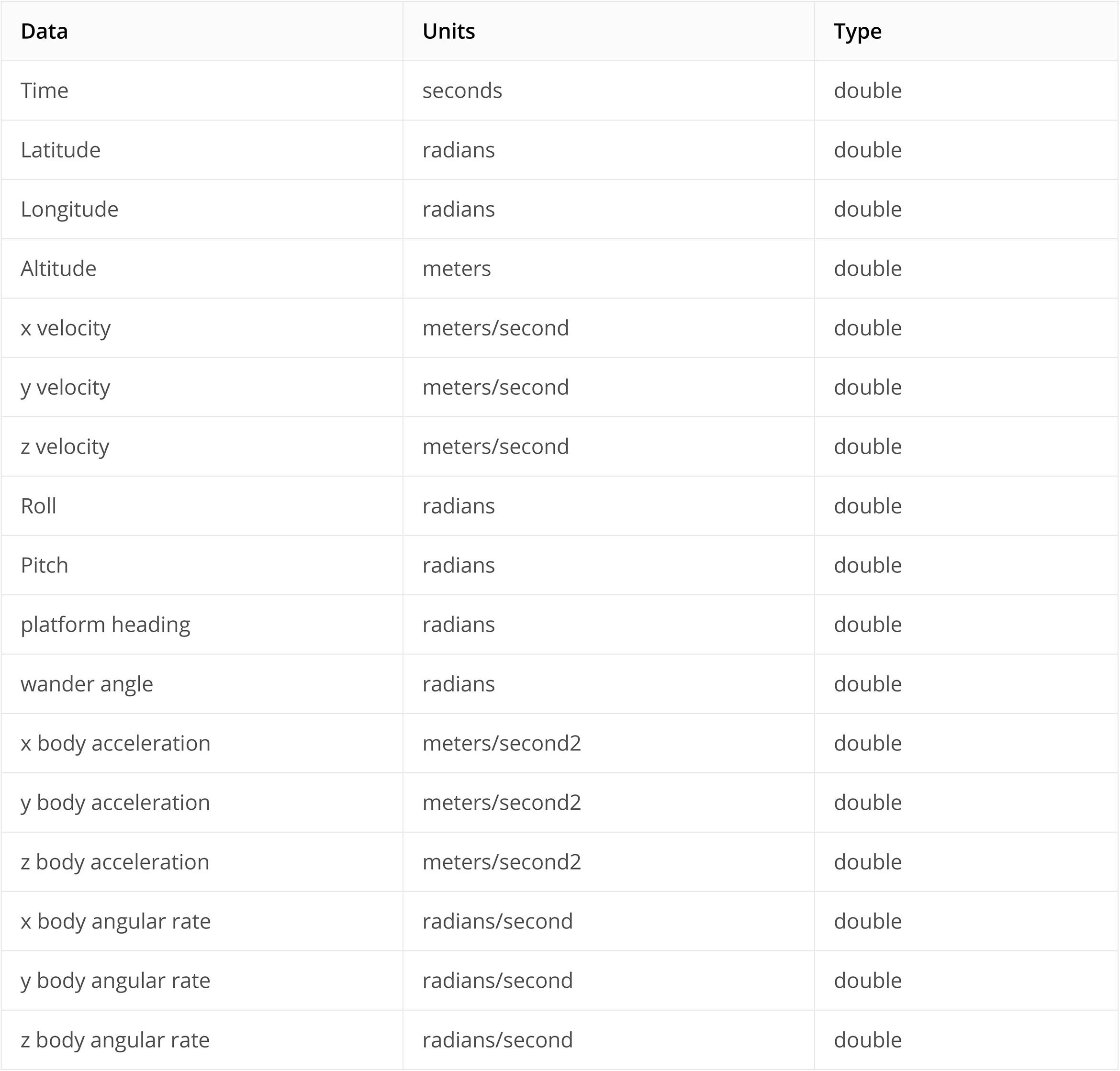
SMRMSG Format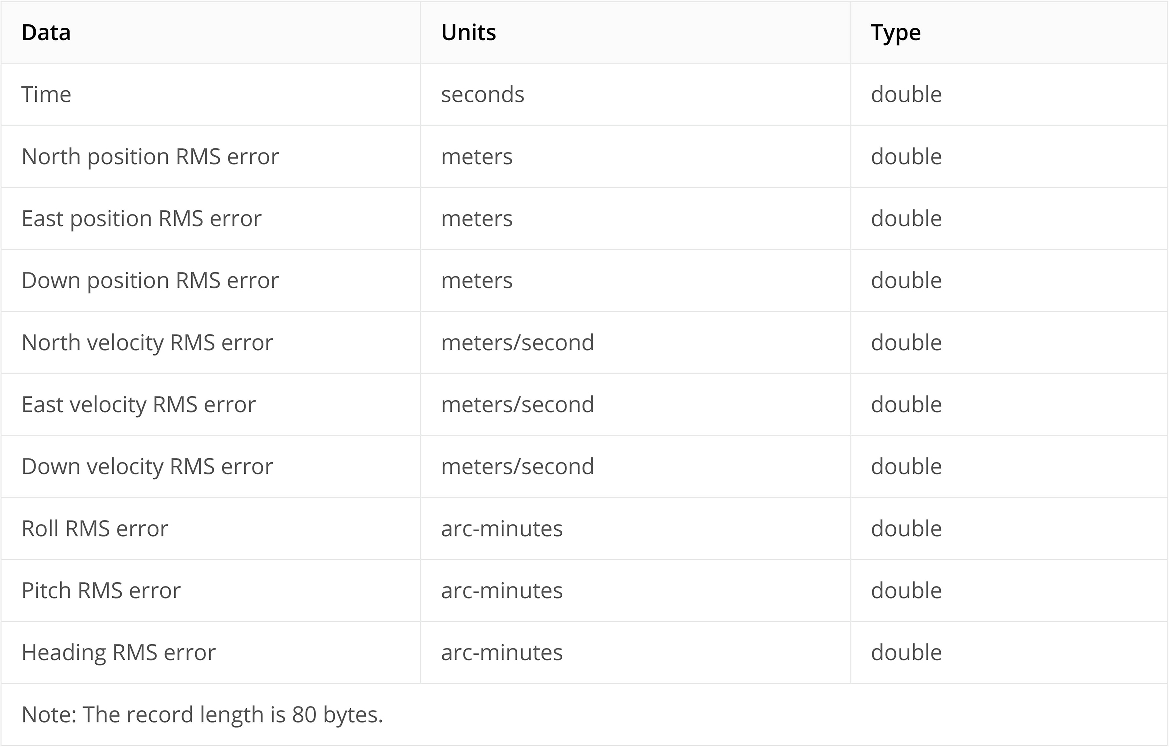
1. Point cloud effective distance: The point cloud that exceeds the distance from the LiDAR will be filtered during post-processing.
2. How to set up a point cloud effective distance: Estimate the maximum straight-line distance between the location of LiDAR and the corresponding target area when collecting data.
3. Under which scenes to set up: When reconstructing a closer measuring area, and when distant background areas are inevitably collected, you can set up an effective distance to get a better result for point cloud.
1. Point cloud accuracy optimization: Optimize point cloud data scanned at different times to make the overall point cloud accuracy higher.
2. When to turn on point cloud accuracy optimization: When it is off, if the results contain obvious layer malposition, turn on the point cloud accuracy optimization feature to fix the problem.
The default coordinate system is WGS84 and can be modified.
You are recommended to separate it into multiple tasks for processing.
The reflectivity of the measured target is between 0 – 255, where 0 to 150 correspond to the reflectivity within the range of 0 to 100% in the Lambertian reflection model; 151 to 255 correspond to the reflectivity of target objects with retroflection properties.
The 3D coordinates, RGB color, reflectivity, GPS timestamp, number of returns, the actual return number, and scanning angle of the points are recorded, along with the total number of points corresponding to each return, the software and version corresponding to the generated results, and the geographic coordinate system.
.pnts, .las, .s3mb, .ply, and .pcd
The calibration route can be designed using 5-heading tilt-shift photography or traditional 5-route oblique photography.
To achieve a more reliable calibration result, the following parameters are recommended:
– Capturing no less than 500 images
– The front overlap is no less than 80%
– The side overlap is no less than 70%
– The proportion of oblique images is not less than 2/3
– A calibration scenario with a large elevation difference area
RTK is not required, but the quality of calibration results can be verified through RTK in connection with checkpoint layout.
If RTK positioning data is available for calibration route collection, the accuracy of checkpoints can be verified based on the results of the calibration route reconstruction by deploying checkpoints in the survey area. If the accuracy meets the required engineering accuracy, the calibration meets the standard.
If no RTK positioning data is available for calibration route collection, it is impossible to quantitatively evaluate whether the calibration result meets the standard. However, this can be verified based on the difference between the initial value and the optimized value of camera parameter focal length f and principal points cx, cy for oblique photography reconstruction after camera calibration. If there is no significant difference, the calibration can be considered as meeting the standard.
How often the load device should be calibrated depends on actual use. It is recommended to calibrate the camera using the latest reconstruction calibration file when there is a significant difference between the initial value and the optimized value of camera parameter focal length f and principal points cx, cy in the reconstruction quality report, and the reconstruction result meets the engineering accuracy requirements.
Currently, no.
No. Currently RGB images are required for 2D multispectral reconstructions.
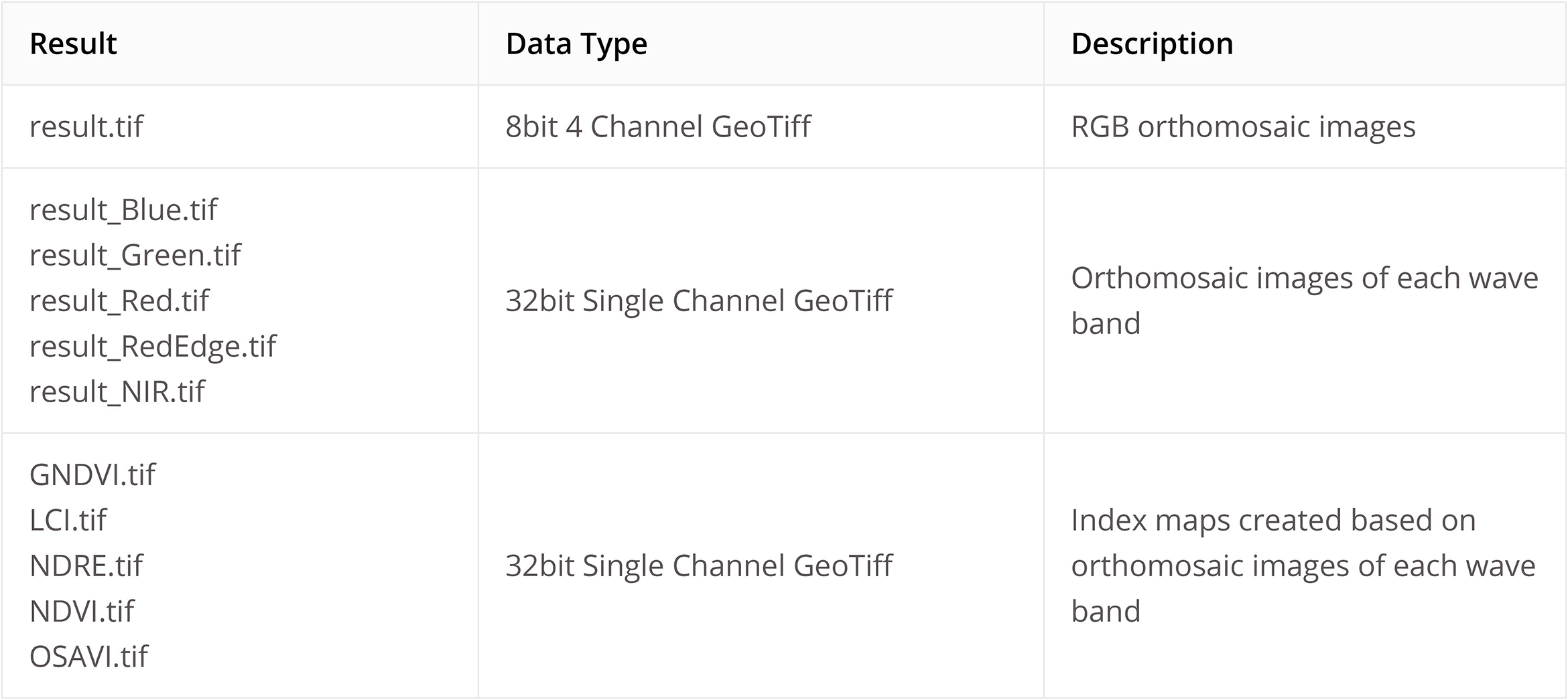
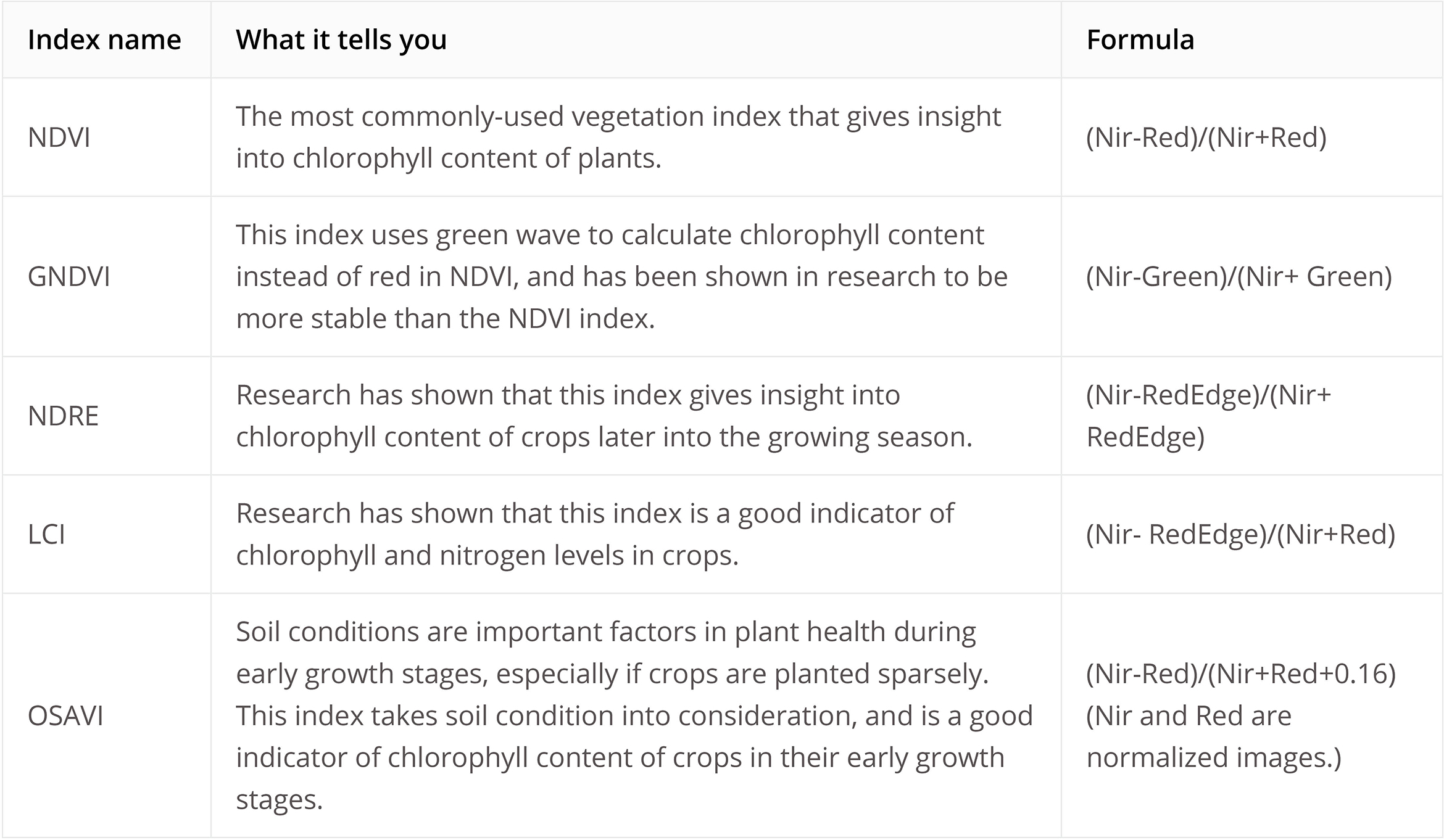
Yes. You only need to import RGB images and images within the bands required by a particular vegetation index to perform a reconstruction.
Yes, before reconstruction, calibration data can be imported for radiometric correction
Up to three sets of calibration board data are supported.
Yes. The default path is C:\Users\***(User Name)\Documents\DJI\DJI Terra. You can modify the path by going to  >>
>>  >> Cache directory.
Yes, the .obj files generated in DJI Terra can be imported into Maya, Blender, SketchUp, and 3ds Max. Look up tutorials for the specific process for each software.
Yes, .b3dm, .osgb, .ply and .obj files generated by DJI Terra are universal file formats and can be embedded into webpages. You can find instructions for embedding each of these formats online.
Theoretically they can be used to reconstruct 3D models although the quality might suffer. They cannot be used to build 2D reconstructions.
Theoretically yes for 3D models, but the results might not be as good as if you were to use DJI drones. The quality of the reconstructions will benefit from GPS or RTK positioning data on the images. Real-time 2D reconstructions are not supported.

1. Check if there has been any hardware changes with the computers bound to the software. Any hard disk location changes or CPU replacements will invalidate the previous binding settings;
2. Check if you have bound any hardware device on a cloud server, such as Alibaba Cloud and Tencent Cloud, which will invalidate the previous binding settings.
1. Check if any other software (or a virus, Trojan horse, adware, etc.) has been installed on your computer that is preventing DJI Terra from establishing an internet connection. This can be solved by resetting the networks of the Windows system.
2. Check if any VPN software has been enabled. If so, disable the VPN or configure the VPN correctly.
You will see the following data in the log:
[GetAvailableFunc] iDate: 1596520841 iCurDate: 1596520513 iEndDate:1596729600
[GetAvailableFunc] Local license out of date.
iDate is the server’s time, and iCurDate is the current time of the user’s computer. The license cannot be used when iDate > iCurDate.
Usually the value of iCurDate should be greater than iDate. It is possible that your computer’s clock is slow. You may try resetting the time. Both Win7 and Win10 support automatic online time calibration. We suggest you enable this feature.